Actuators are the muscles of a machine, or in our case, a robot. They convert control signals into physical motion in the real world. Those control signals can be electrical, hydraulic, or pneumatic, depending on the actuator type.
They don’t get the hype as much as artificial intelligence did, but actuators are surely very, very crucial for how most devices were invented. While writing this article, it’s summertime, I’m using a small fan to cool myself during work. This fan uses a motor, which is an actuator.
You name it: industry, home, school, actuators are super important!! Whether you’re making a robotics arm, a simple car, a quadruped robot, or even your own 3D printer as a robotics project, you will need some motors: either servo motors, DC motors, stepper motors, etc. These are all actuators.
To simply put it: “If it produces motion, it’s an actuator.”
How does an actuator work?
Same as with sensors, each actuator has its own way of functioning, but they still follow a general pattern.
First is power. We need a source of energy to convert into mechanical energy, and it needs to be controllable. In automation, a controller acts as the brain. It sends an electrical signal to a driver (next paragraph). Sometimes this signal powers the actuator directly (if it’s low current), or it’s just control data while the actuator gets its power from another source.
Now back to the driver, it’s the chip or board that controls the actuator. Let’s take a DC motor as an example. This type of motor spins once powered up, and its rotational direction depends on the direction of the current. If the current flows one way, the motor rotates in one direction. Reverse the current, and the motor spins the other way.
To automatically control direction, we use a motor driver. The signal from the controller could be a serial command or just two logic pins. For example:
- If pin 1 is active → rotate left
- If pin 2 is active → rotate right
So to sum up: the driver is the module that translates your control signals into actual motion behavior.
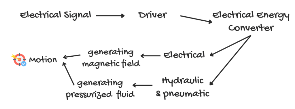
Next, is converting the electrical energy. This part differs based on the actuator type.
Electrical actuators
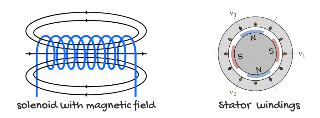
In electrical actuators, the controller feeds current into the stator windings, which creates a rotating magnetic field. (In electromagnetism, a current flowing through a solenoid produces a strong and nearly uniform magnetic field inside, with weaker, looping field lines on the outside.) This field interacts with the rotor’s magnets, making it spin.
Hydraulic/pneumatic actuators
In hydraulic or pneumatic actuators, the same control signal activates a pump or proportional valve, generating pressurized fluid or air. This pressure then moves a piston or vane, resulting in linear or rotary motion. (The resulting force depends on fluid pressure and piston area, based on Pascal’s Law.)
To sum up in a diagram:
Some Actuators to Mention
| Actuator | How it works (one-liner) | Where you see it in the real world |
|---|---|---|
| Brushed DC motor | Current + brushes → rotor spins | Drive wheels on hobby robots, extruder motor on a Creality Ender-3 |
| Brushless DC (BLDC) | Electronic commutation of fixed coils → rotor spins | Drones, e-bike motors |
| Stepper motor | Energize coils in sequence → discrete angle steps | X/Y axes of CNC laser or 3D printer |
| Hobby servo | DC motor + gears + pot → holds commanded angle | Robotic arms (as joints) |
| Linear screw actuator | Motor turns lead/ball screw → nut moves linearly | Z-axis lift on small CNC mills |
| Hydraulic cylinder | Pressurized oil pushes piston → heavy linear force | Excavator arm joints |
| Pneumatic cylinder | Compressed air pushes piston → fast linear strokes | Pick-and-place grippers on assembly lines |
How to choose an actuator like an engineer (for your robotics project)
I will not include the hydraulic or pneumatic actuators for now, as for these are found mainly on industrial automation or robotic arms with heavy loads. We are only going to see the case for electrical rotation based actuators so you can better understand. Here I’ll give you a flow of what you can expect:
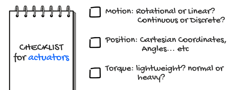
1. What kind of motion do I need?
- If continuous rotation, probably for a fan or a wheel -> DC motor or brushless motor (BLDC for short)
- If precise angular control (like building a robotic arm) -> Servo motor or stepper motor
- If precise linear movement (like controlling a hotend) -> stepper motor + leadscrew/belt
2. Do I need position feedback? (on which coordinates/angles I’m in)
- If yes, and simple -> Servo motor (built-in feedback)
- If yes, and higher precision -> Stepper or DC motor with an encoder (to mesure RPM) or closed-loop servo
- If no, just spin -> Brushed DC or brushless motor
3. How heavy is the load? (how much torque is needed?)
- If lightweight -> Standard hobby motors (like SG90)
- If medium (building a simple pick-and-place) -> NEMA 17/23 stepper motor, geared servo
- if heavy (CNC head, 3d printer hotend) -> Larger stepper motor (NEMA 23/34)
In my first year, I worked with a team on a CNC laser plotter project. Our goal was to feed it a design and make it draw that shape onto wood.
We used LaserGRBL as the program to send G-code commands to the robot. For motion, we chose two NEMA 23 stepper motors, one for the X-axis and one for the Y-axis. Timing belts and pulleys helped us transmit the motion.
Our laser module was just 0.5W, enough to mark the surface but not enough to burn. We chose it on purpose because our prototype didn’t have proper safety protections (and I learned that the hard way when the engineers evaluating our project pointed it out).
To control the motors, we used two TB6600 stepper drivers. These supported microstepping and handled higher current, which made them perfect for NEMA 23 motors. Everything was connected to an Arduino Uno, which got its instructions from the laptop.
In the end, the machine worked.
It wasn’t the fastest or the cleanest build. Just a simple prototype. But we turned code into motion, and that’s what actuators are all about.
No comments yet