If you are studying robotics, you’ve probably heard the word “microcontroller,” or “Arduino” to be more specific. Back then, in our first learning sessions, I saw my classmates making a straightforward conclusion that Arduino = microcontroller. There are two big misconceptions here:
- Arduino is not a microcontroller. It’s a company that makes single-board microcontrollers (Arduino Uno, Arduino Nano, etc.). Those boards contain a microcontroller, mostly made by Atmel. For example, the Arduino Uno is a board that contains the ATMega328P microcontroller, made by Atmel.
- Not every microcontroller falls under the Arduino or Atmel family. There are many microcontrollers out there such as STM32, ESP8266, and more.
To help you understand better, take this standard definition:
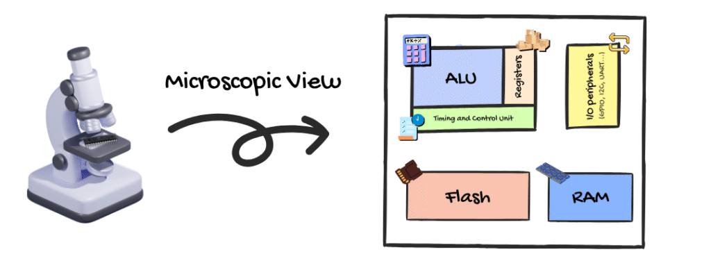
A microcontroller is a chip that contains a microprocessor, alongside memory (RAM and ROM), and I/O peripherals (I/O stands for Input/Output). The difference between normal microprocessors and the ones inside microcontrollers is that microcontroller processors are designed to be very small and consume less power, which makes them less performant too.
In this article, we will go through some technical details that most people don’t cover. That includes the architecture of a microcontroller, how it executes instructions, and how the code we write in the IDE goes into the chip itself.
The Structure of Microcontrollers
Back to the definition; A microcontroller is composed of a microprocessor (we explained the structure of a microprocessor in a previous article, feel free to check it out), memory, storage, and I/O peripherals, all in a single chip. A microprocessor also depends on memory and I/O peripherals, but as external components.
This means that a microcontroller also has an ALU, registers, a timing and control unit, buses, and everything that a microprocessor has. But because of the small size and its way of leaning to being generalist, the performance gap is huge.
If you do a quick search, you’ll find that most microcontrollers have a clock speed in the MHz range (16 MHz for ATMega328P, 133 MHz for RP2040), while most microprocessors integrated into a board instead of a chip reach GHz-level speeds. The same logic applies to other components too.
Besides the internal structure, the outer structure is designed in a way that allows a wider range of people to use microcontrollers easily. This is achieved through pins and a datasheet or pinout diagram explaining what each pin does. There are digital pins, analog pins, power pins, ground pins, serial communication pins, and so on.
Still, both MCUs and MPUs follow a much more intuitive structured approach, the difference can be very big when compared to an FPGA for example.
The Process of Code to Hardware
Let’s take the case of using an Arduino Uno with an ATMega328P MCU to demonstrate the process. The same logic applies to every microcontroller.
1. Writing and Compiling
You open up the Arduino IDE or PlatformIO, and you write some code, like this one:
void setup() {
  pinMode(13, OUTPUT);
}

void loop() {
  digitalWrite(13, HIGH);
  delay(1000);
  digitalWrite(13, LOW);
  delay(1000);
}
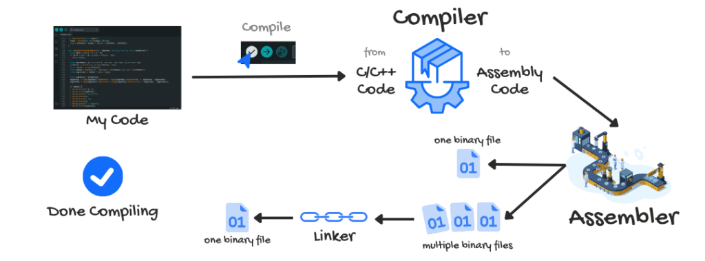
This code is written mainly in C, a low-level programming language you can read, not the chip. In electronics, the only language spoken is binary, or what we call machine code. So we need a translator that can convert our C code into instructions the ATMega328P can understand. This is where the compiler software package comes in.
The compiler software package consists of three tools: Compiler – Assembler – Linker.
For Arduino IDE, the compiler is called AVR-GCC. It translates all the code you’ve written (including headers/libraries via #include) from C language into assembly. Then the assembler transforms the assembly code into binary, along with the data and information it needs to execute instructions in memory.
Sometimes, the assembler creates multiple files. In that case, the linker combines all the assembled machine code and object files into a single file.
At the end, we get a .hex file that’s ready to be delivered to the microcontroller.
2. Uploading to the Microcontroller
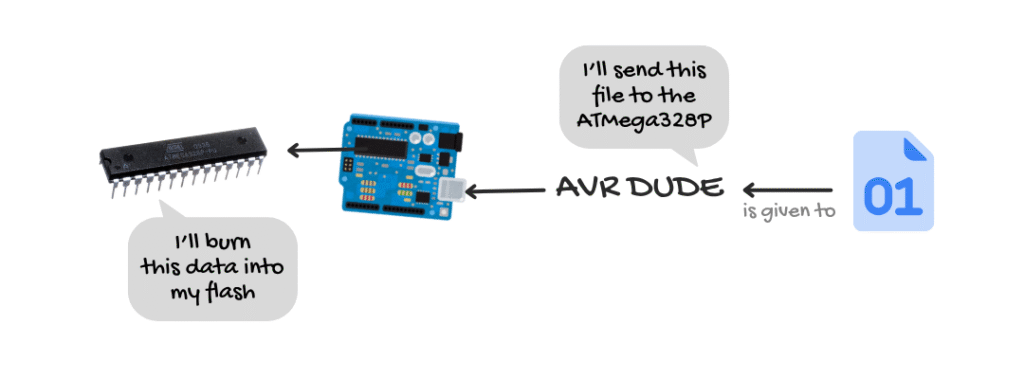
Everything so far happens when you click the Compile button. The same process is triggered if you hit Upload, except now there’s the step of sending the file to the chip.
Meet AVR Dude (Dude = Downloader/UploaDEr), our deliverer. It’s a piece of software that checks the COM port your Arduino board is connected to, then sends the .hex file directly to the microcontroller over USB.
The code file is now inside the microcontroller and is handed over to the bootloader.
To explain the bootloader in general: when you turn on a PC, the BIOS is the first firmware that runs. The BIOS then looks for the drive with the bootloader, which loads the operating system. (Linux community, you might know GRUB, yes, it’s a bootloader)
In microcontrollers, there’s no BIOS. So the chip directly jumps to the bootloader. The bootloader then takes your code and burns it into flash memory (or ROM), sector by sector. In the case of the ATMega328P, the flash memory is around 32 KB.
Then the microcontroller jumps to the starting address of your new program. (Side note: the bootloader is activated on reset (when you click the red button on the Arduino Uno), or on power-up)
3. The Instruction Cycle
I already explained this in the microprocessor article, feel free to check it out for more details.
In simple terms, the microcontroller fetches the instruction from memory using the program counter, then the control unit identifies the instruction and sends it to the ALU to execute. The result is sent through communication protocols like GPIO.
This cycle goes on until it reaches the end. If you’re in the loop() function, the code inside that block keeps re-executing.
Standalone Microcontrollers vs Microcontrollers on Development Boards
A standalone microcontroller is just the raw silicon chip, like the ATMega328P, STM32F103C8T6, or PIC16F877A, with those pins that make them look like an insect (great for scaring your friends, I know).
You can’t just plug in a USB cable. There’s no voltage regulator, no reset button (just a reset pin).
They give you full freedom to use them on any PCB, breadboard, or even embedded directly with other components. They’re also much cheaper compared to MCUs on development boards, and you don’t waste a resistor or any other component on features you don’t need.
Of course, this freedom comes at a cost, you’re not going to work comfortably with a standalone microcontroller unless you really, really know what you’re doing.
A microcontroller on a development board is the same chip, but integrated into a board that’s designed specifically for it. It comes with everything you need so you as a learner can focus on the code and the external components.
The pins are distributed in a more readable and accessible way. here’s what they look like on an Arduino Uno:
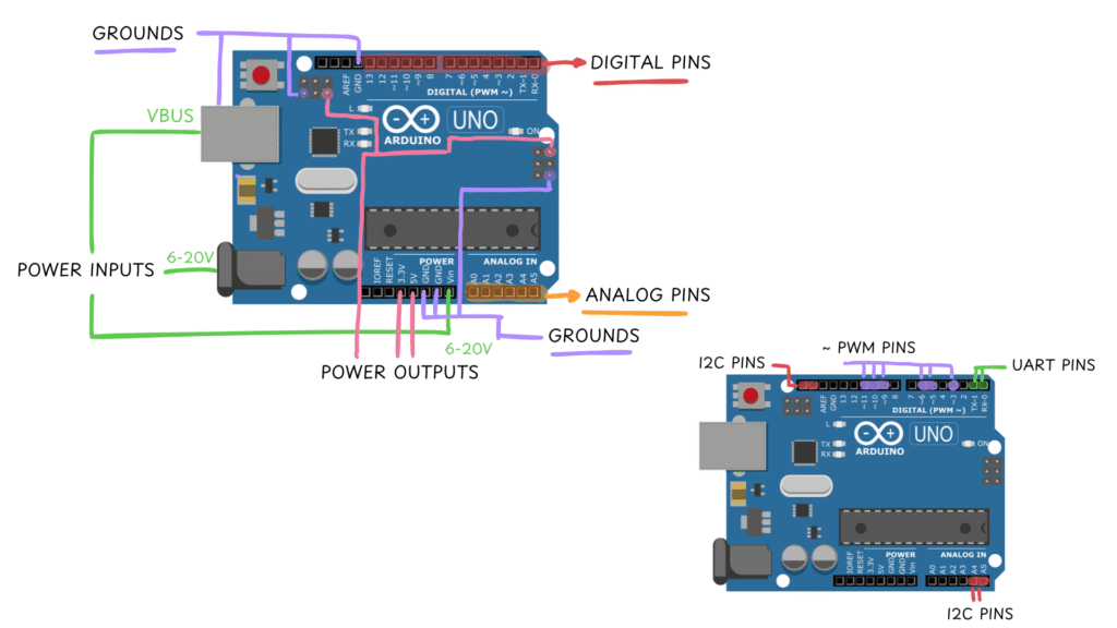
Development boards also include extra debugging features — like a built-in LED, LEDs for UART communication (TX and RX), power-on LEDs, buzzers, and so on.
Some great boards include: Arduino Uno, NodeMCU, STM32 Blue Pill, Teensy, Raspberry Pi Pico, and many more.
Phew! So many details for just a microcontroller, I know. And it can be a bit hard to grasp at first. But still, I hope this article helped you understand what’s behind that simple board you’re using. If there’s any part you didn’t understand, just drop your question below, I’ll gladly answer it 🙂
No comments yet